Antmicro’s open source simulation framework, Renode, was built to enable simulating real-life scenarios - which have a tendency to be complex and require hybrid approaches.
That’s why, besides other things, the Renode 1.7.1 release has introduced an integration layer for Verilator, a well known, fast and open source HDL simulator, which lets you use hardware implementations written in Verilog within a Renode simulation.

When you are working on ASIC or FPGA IP written in an HDL, forming a part of a bigger system with unknowns both in the hardware and software, many things can go wrong on multiple levels. That’s why ultimately it's best to test it within the scope of the full system, with drivers and test software, in a real-world use case. Simulating complete platforms with CPUs and all peripherals using actual HDL simulation, however, can be too slow for effective software development (and sometimes downright impossible, e.g. when access to the entire SoC’s HDL is not available). Renode models will give you better speed and flexibility to experiment with your architectural choices (as in the security IP development example of our partner Dover Microsystems) than HDL, but there might still be scenarios where you could quickly try to directly use complex peripherals you already have in HDL form before going on to model them in Renode. For these use cases Antmicro has enabled the option of co-simulating HDL in Renode using Verilator. Co-simulating means you’re only ‘verilating’ one part of the system, and may in turn expect a much faster development experience than with trying to perform an HDL simulation of the whole system.
In the 1.7.1 release of Renode you will find a demo which includes a ‘verilated’ UARTLite model connected to a RISC‑V platform via the AXI4-Lite bus running Zephyr.
Integration layer overview
The integration layer was implemented as a plugin for Renode and consists of two parts: C# classes which manage the Verilator simulation process, and an integration library written in C++ that allows you to turn your Verilog hardware models into a Renode ‘verilated’ peripheral.
The ‘verilated’ peripheral is compiled separately and the resulting binary is started by Renode. The interprocess communication is based on sockets.
How to make your own ‘verilated’ peripheral
An example ‘verilated’ UARTLite model is available on Antmicro’s GitHub.
To make your own ‘verilated’ peripheral, in the main cpp file of your verilated model you need to include C++ headers applicable to the bus you are connecting to and the type of external interfaces you want to integrate with Renode - e.g. UART’s rx/tx signals. These headers can be found in the integration library.
// uart.h and axilite.h can be found in Renode's VerilatorPlugin
#include "src/peripherals/uart.h"
#include "src/buses/axilite.h"
Next, you will need to define a function that will call your model’s eval function, and provide it as a callback to the integration library struct, along with bus and peripheral signals.
void eval() {
#if VM_TRACE
  main_time++;
  tfp->dump(main_time);
#endif
  top->eval();
}

void Init() {
  AxiLite* bus = new AxiLite();

  //==========================================
  // Init bus signals
  //==========================================
  bus->clk = &top->clk;
  bus->rst = &top->rst;
  bus->awaddr = (unsigned long *)&top->awaddr;
  bus->awvalid = &top->awvalid;
  bus->awready = &top->awready;
  bus->wdata = (unsigned long *)&top->wdata;
  bus->wstrb = &top->wstrb;
  bus->wvalid = &top->wvalid;
  bus->wready = &top->wready;
  bus->bresp = &top->bresp;
  bus->bvalid = &top->bvalid;
  bus->bready = &top->bready;
  bus->araddr = (unsigned long *)&top->araddr;
  bus->arvalid = &top->arvalid;
  bus->arready = &top->arready;
  bus->rdata = (unsigned long *)&top->rdata;
  bus->rresp = &top->rresp;
  bus->rvalid = &top->rvalid;
  bus->rready = &top->rready;

  //==========================================
  // Init eval function
  //==========================================
  bus->evaluateModel = &eval;

  //==========================================
  // Init peripheral
  //==========================================
  uart = new UART(bus, &top->txd, &top->rxd,
  prescaler);
}
As part of the last step, in the main function, you have to call simulate, providing it with port numbers, which are passed as the first two command-line arguments of the resulting binary.
Init();
uart->simulate(atoi(argv[1]), atoi(argv[2]));
Now you can compile your project with Verilator:
verilator -cc top.v --exe -CFLAGS "-Wpedantic -Wall -I$(INTEGRATION_DIR)" sim_main.cpp $(INTEGRATION_DIR)/src/renode.cpp $(INTEGRATION_DIR)/src/buses/axilite.cpp $(INTEGRATION_DIR)/src/peripherals/uart.cpp

make -j 4 -C obj_dir -f Vtop.mk
The resulting simulation can be attached to the Renode platform and used in a .repl file as a ‘verilated’ peripheral.
uart: Verilated.VerilatedUART @ sysbus <0x70000000, +0x100>
simulationFilePath: @verilated_simulation_file_path
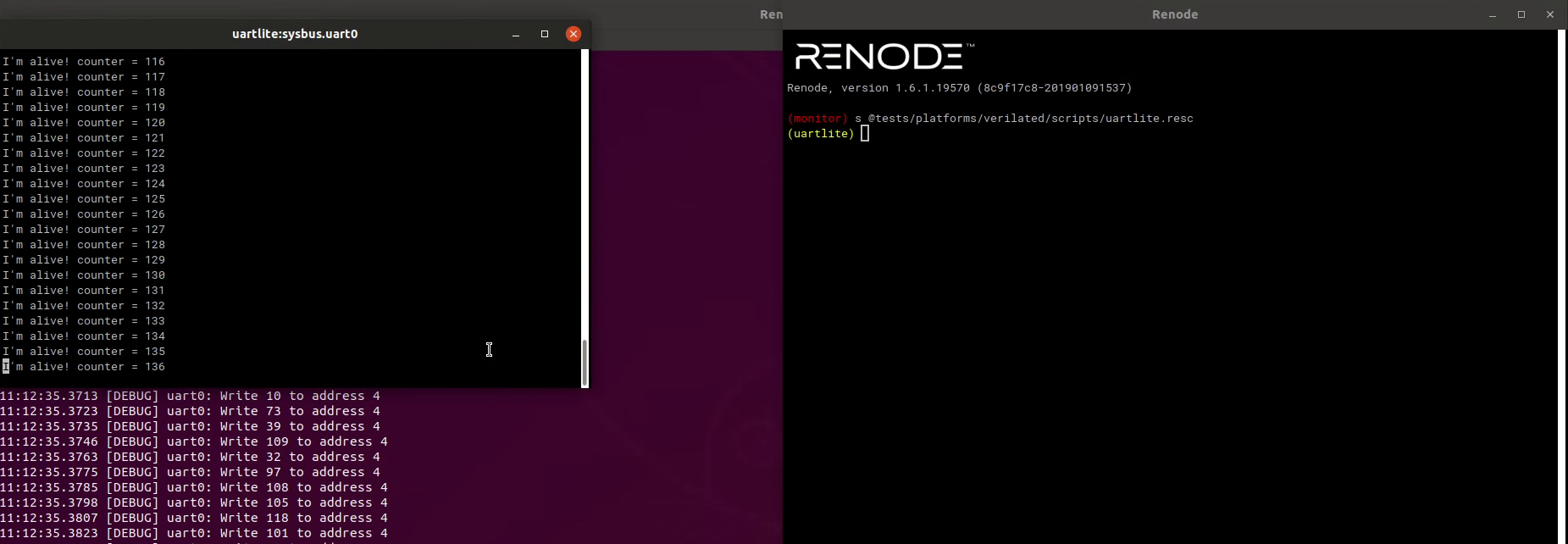
frequency: 100000000When you load such a platform in Renode and run a sample application, this is the output you'll see. Keep in mind that the UART window displays data printed by the verilated peripheral.
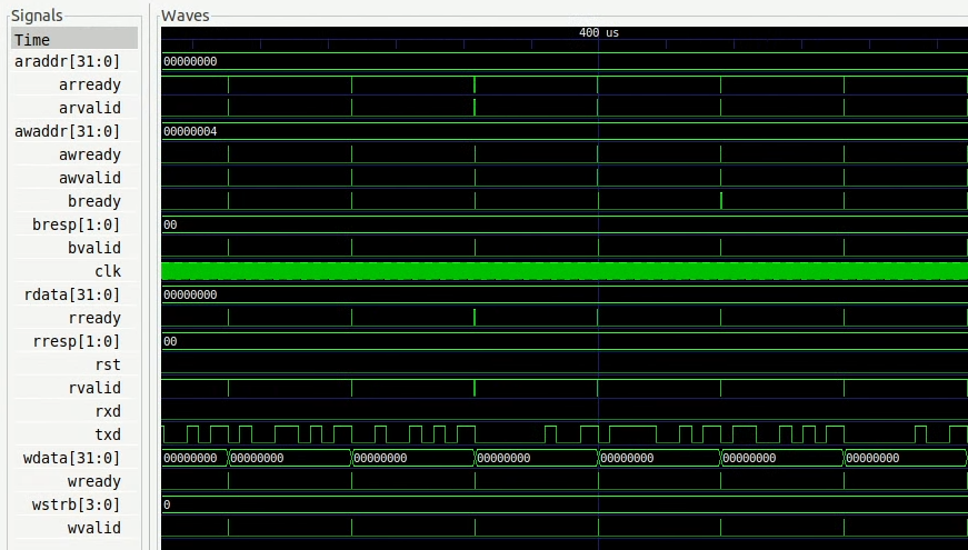
You can also enable signal trace dumping by setting the VERILATOR_TRACE=1 variable in your shell. The resulting trace is written into a vcd file and can be viewed in e.g. GTKWave viewer.
Renode’s powerful co-simulation capabilities
Whether you are working on a new hardware block or you want to reuse the HDL code you have, Renode’s co-simulation capabilities allow you to test your IP in a broader context than just usual hardware simulation, connecting it to entire RISC‑V, ARM or other SoCs even without writing any model.
You can use Renode’s powerful tracing and logging mechanisms to observe your peripheral’s behavior when used by an operating system of your choice, in an environment of your choice - be it a full-blown Linux-capable multi-core system or a small RTOS-ready SoC, or even a mix of those options.
Want to debug your driver via GDB but your target FPGA does not have a debugger connector? Or maybe it is just too small to contain the whole SoC you’d like to run? Perhaps you’d like to run a Python script to create a nice graph on each peripheral access? Renode has got you covered with all these features available out of the box.
If this sounds interesting, you can start using Renode’s co-simulation capabilities today or let us know about your use case directly so that we can potentially help you improve your simulation-driven workflow - all you need to do is get back to us at contact@renode.io.